Understanding and Reading Modulation Transfer Function (MTF) Charts
The Modulation Transfer Function (MTF) is a fundamental metric used to assess the imaging performance of vision systems such as lenses, industrial cameras, and detectors. It quantifies how well a vision system can transfer contrast from the object to the image at different spatial frequencies, effectively describing the system’s resolution and image quality.

Choosing the right machine vision lens can be challenging because lens performance is not easily determined by simple measurements. To assess this, we provide MTF (Modulation Transfer Function) information which is available in Lens Resolution Data V1.7 in Downloads. This file contains numerical MTF data that quantify a lens's ability to transfer contrast from an object to its image (please note that MTF charts are not included).
Table of contents
How to read a MTF chart
MTF data is typically presented in one of two graphical formats. While they look different, they often present the same underlying data. Many MTF charts include a diffraction limit curve representing the theoretical maximum contrast transfer for a perfect vision system. Real lenses perform below this limit due to aberrations and manufacturing imperfections.
Measuring Spatial Frequency in MTF Charts
Modulation Transfer Function measures the ratio of image contrast to object contrast as a function of spatial frequency, usually expressed in line pairs per millimeter (lp/mm).
Spatial frequency corresponds to the level of detail in the object: low frequencies represent large, coarse features, while high frequencies correspond to fine details.
The MTF value ranges from 0 to 1 (or 0% to 100%), where 1 means perfect contrast transfer and 0 means no contrast is transferred at that frequency.
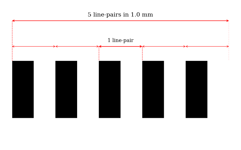
Line pairs per millimeter (lp/mm) is the standard unit for spatial frequency in MTF charts.
- One line pair consists of one black and one white line, and the number of such pairs that fit into one millimeter determines the spatial frequency. For example, 1 lp/mm means there is one pair of lines (one black, one white) in each millimeter of the image. At 5 lp/mm, there are 5 pairs (10 lines) per millimeter, and so on.
- Higher lp/mm values represent finer details. As the number of line pairs per millimeter increases, the ability of the lens to maintain contrast between the lines decreases, which is reflected in the downward slope of the MTF curve.
- The highest spatial frequency a lens can resolve—where the MTF value drops to nearly zero—is called the cut-off frequency. This is a key indicator of the lens’s maximum resolving power

Decoding the Lines: Sagittal vs. Meridional (Tangential)
On most MTF charts, you will see two lines for each frequency: a solid line and a dashed/dotted line. These represent two different orientations of the test pattern.
- Sagittal (S) Lines (Solid): Represent test lines that test lines run outward from the center of the image. This is sometimes called "radial".
- Meridional (M) or Tangential (T) Lines (Dashed/Dotted): Represent test lines oriented perpendicularly to the sagittal lines.
The separation between the sagittal and meridional lines indicates astigmatism, an aberration where the industrial camera lens blurs detail differently depending on its orientation. The closer these two lines are to each other, the more uniform the lens's performance and the lower its astigmatism. A wide gap signifies that details will be blurred unevenly, which can be problematic for stars or fine textures.
In short: the closer the two curves are, the better and more uniform the image quality.
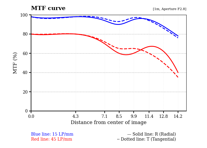
Type 1: MTF vs Image height (Distance from the center of image)
- X-axis describes the distance from the center of the image, measured in millimeters (mm). The far right of the axis represents measurements at the edge or corner of the sensor, useful for evaluating lens performance toward the frame boundaries.
- Y-axis describes the contrast values from 0 to 100%, higher values mean better transmission of contrast from subject to image. Lines closer to the top of the graph indicate superior lens performance, sharper and higher-contrast images.
This chart indicates that:
At the image center (0 mm):
- Both blue and red lines start high (~95% for 15 LP/mm, ~80% for 45 LP/mm).
This means the lens is very sharp at the center, with good contrast and fine detail reproduction.
Towards the mid-frame (around 7–10 mm):
- Blue line (low frequency) stays high (~90%), meaning contrast is well preserved across the frame.
- Red line (high frequency) drops more noticeably (~60%), meaning fine detail resolution is lower at the edges.
At the image edges (12–14 mm):
- Blue line drops slightly but still decent (~80%).
- Red line falls sharply (~30–40%), showing loss of fine detail and sharpness near the edge.
- The separation between radial and tangential lines shows astigmatism or field curvature.
This lens performs very well in the center with excellent sharpness and contrast. Low-frequency contrast remains strong across the frame. Fine details degrade towards the edges, especially at higher frequencies. The difference between radial and tangential suggests edge softness or astigmatism.

Type 2: MTF vs Spatial Frequency
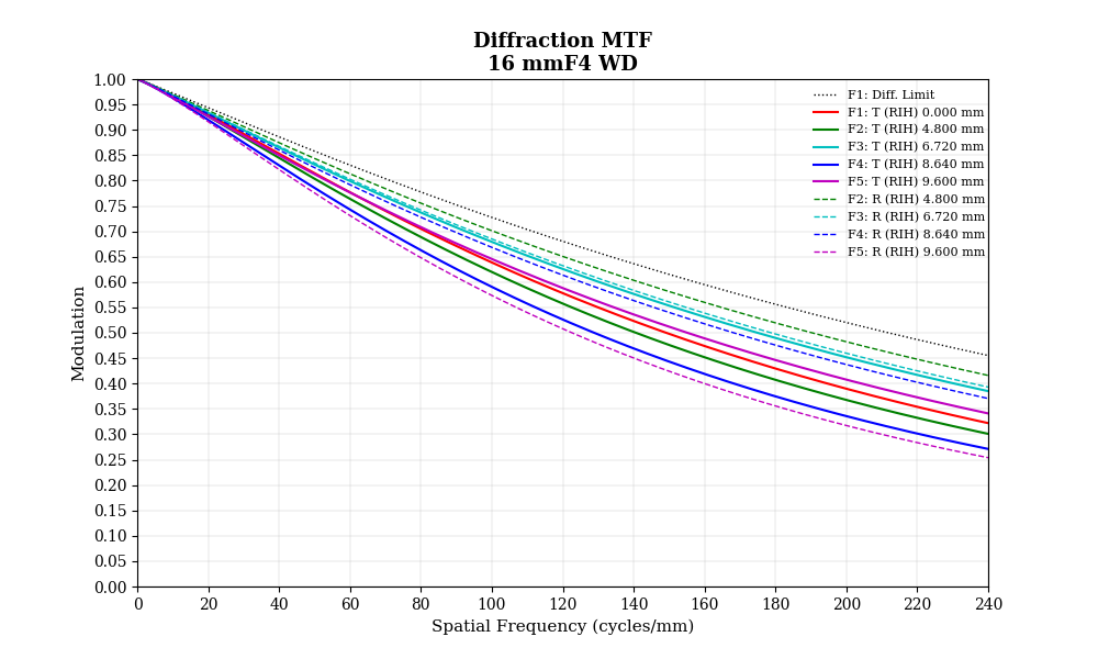
MTF curves are often provided for different field points such as on-axis (center), mid-field (e.g., 70% of the image radius), and edge (full-field). Comparing these curves reveals how lens performance varies across the image field.
- X-axis represents spatial frequency, typically in lp/mm. Increasing values move from coarse to fine details.
- Y-axis shows the modulation or contrast transfer, usually as a percentage or normalized value from 0 to 1.
- The MTF curve typically starts near 1 (or 100%) at low spatial frequencies and decreases as frequency increases. A lens with a higher MTF curve at higher lp/mm can resolve finer details with better contrast.
Unlike the first MTF chart (which measured performance at 15 and 45 line pairs per mm at different field positions), this one shows modulation transfer across a wide range of spatial frequencies for different field heights.
At low spatial frequencies (left side, ~10–40 cycles/mm):
- Most curves are above 0.9, close to the diffraction limit which means good contrast across the frame.
At mid frequencies (~80–120 cycles/mm):
- Center (red) stays close to 0.7–0.8.
- Mid/edge curves (blue, purple, pink) drop more, showing a falloff in fine detail reproduction as you move toward the edges.
At high frequencies (>150 cycles/mm):
- The diffraction limit curve falls, showing the aperture is diffraction-limited at F4.
- The real curves (especially near the edges) drop faster than the center, meaning corner resolution is significantly softer at very fine detail.
Radial vs Tangential:
- In the center, R and T are almost identical.
- Toward the edges, differences appear (R vs T spread apart), indicating astigmatism or field curvature.
This lens has excellent center sharpness at F4, maintaining good detail transfer close to the diffraction limit. Toward the edges, contrast at fine detail frequencies drop, with sagittal/tangential differences showing astigmatism.

Key Takeaways from MTF Charts:
MTF charts are one of the best tools for objectively evaluating the resolution and contrast performance of a lens. By learning to read them, you can move beyond marketing claims and make data-driven decisions.
Note that no lens is perfect, and the way they refract and focus light can lead to various imperfections in the resulting image. These imperfections are known as lens aberrations and lens distortion.
Understanding these phenomena is essential for machine vision systems designers and integrators to choose the right lens and optimize industrial camera system performance, avoiding potentially wasted investment on unsuitable components.
Interested in the range of components for machine vision systems we offer at VA Imaging, or have specific questions? Don't hesitate to get in touch. Simply fill in the contact form below, and a member of our team will be happy to assist.


