Analysis and Defect Detection of Copper Parts Using Machine Vision
For many semi-finished material products suppliers, a copper tube analysis is a part of the quality control system. Using machine vision hardware and the correct software, the tube can be inspected for surface defects, dimensional errors, sizing, accuracy and other anomalies.

In this project, our customer was looking for a high-resolution industrial camera to capture the copper tube as it moves along the production line, a high resolution and high precision lens and proper lighting since it was essential to highlight the surface defects. The customer was examining fins that resemble the scales of a fish. A single fin is approximately 0.4mm in size and it overlaps with adjacent fins. What they mainly wanted to see was the boundaries between the fins, as those need to be distinguished in the image. Hence, it was important to have a clearly visible structure. The gap between the fins varies between 20 to 100 micrometers.
Table of contents
Which Camera to choose for inspecting copper tubes?
A high-resolution camera was needed to be able to have a clear visibility of the boundaries between the fins. This industrial camera was chosen to analyze the pattern of this tube. While making the decision on the machine vision hardware, there were several points that needed to be considered. First, we chose a global shutter camera, since the tube was moving slowly. Second, we decided on a monochrome camera, since the tube had a highly reflective material, and a monochrome camera is three times more light sensitive compared to other cameras. Lastly, a USB3 camera was chosen for this project, due to camera and PC were less than 4.6 meters away in distance. All these characteristics come to life in our IMX 542 Mono Camera, offering an ideal machine vision solution for this project.
Which lens to choose for detecting defects in copper tube analysis?
Our customer was aiming to achieve distortion free images to provide consistent image quality and accurate measurements, hence chose to use a telecentric lens for this project.
Moving on, the decision was needed to be made between a 1x and 2x magnification for these telecentric lenses. In the end, we settled on our 2X magnification telecentric lens. The reason for choosing this lens was that the 2x magnification makes it easier to visualize the smaller details, which would help to clearly see the very small gaps between the fins, which are only 20 micrometers wide.
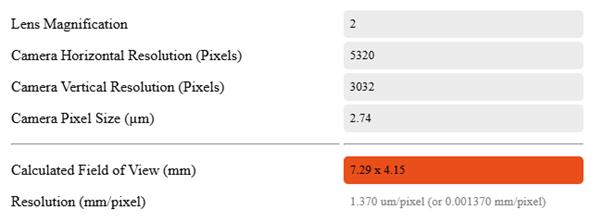
Due to the working distance of the telecentric lens being 110m, our customer was suggested to rearrange their working distance, which was previously 65mm. With the help of our lens calculator, we confirmed that our customer was able to achieve the ideal Field of View (FOV) for their project of 7.29 x 4.15mm.

What Role Does Lighting Play in copper tube analysis?
Machine vision lighting had a very important role in this application. As mentioned before, our customer was aiming to eliminate the reflection caused by the material. Keeping this in mind, we recommended our dome light as a solution to this problem.
Dome lights are perfect for machine vision applications that require even, diffuse illumination, especially for surface inspections tasks just like this application. These lights are commonly used to capture small details and defect detection on highly reflective surfaces, without creating any harsh shadows.
Which software to pair with your hardware for copper tube analysis?
As the ideal machine vision hardware was decided on, next step was to help our customer choose the correct software to complement their machine vision setup. Our recommendation was Zebra Aurora Vision Studio 5 for this project. Initial step for the customer was to download the Lite version, which is a great option to explore and learn more about the software to see if it is a good fit for their project goals for free. One thing to keep in mind is that the Lite version does not support live image capture, however saved images can still be used to test the program. After testing, our customer confirmed that the software would be a good fit for their machine vision application. At this stage, we offer a 30-day trial of the full version of Zebra Aurora to make sure that the customer is confident with their software choice.
With Zebra Aurora, users can capture images from their chosen industrial cameras, lenses, and machine vision lighting setup, and analyze them directly in the software to detect any visual defects. Zebra Aurora is designed specifically for vision engineers who are aiming for powerful results without spending time on programming. It offers a variety of software packages to match a range of requirements.
In addition, our technical support team hosts quarterly training sessions and are happy to assist you in reviewing your images and documentation to create free example programs to get you started quickly.
How can we help you?
As VA Imaging, we are aware that every project is different from each other. Your Field of View may be larger or smaller, you might be handling different kinds of materials, you might have questions about which camera to use, or which resolution is needed to capture the details you need. At VA Imaging, we are here to help you with every step of your machine vision project. Our team can guide you on choosing the right machine vision hardware and software.
Fill out the form below to connect with one of our machine vision experts, who are looking forward to helping you find the best machine vision solution for your project.


