I/O-Steuerung: Wie man eine Machine Vision Kamera mit einem Trigger-Sensor hardwaremäßig auslöst und wie man Machine Vision-Lichter auslöst.
Wenn eine schnelle Bedienung erforderlich ist, muss der Auslösesensor sehr schnell reagieren. Der Auslösesensor ändert die Spannung (Elektrizität) an den angegebenen Pins des I/O-Anschlusses der Kamera.
Inhaltsverzeichnis
1. So funktioniert die Hardware-Auslösung
Wenn ein schneller und präziser Betrieb erforderlich ist, muss der Triggersensor sofort reagieren. Er funktioniert, indem er die Spannung an bestimmten Pins des I/O-Anschlusses der Kamera ändert und so der Kamera signalisiert, ein Bild aufzunehmen.
Trigger-Signaltypen: Rising Edge vs. Falling Edge
- Rising Edge: Die Spannung wechselt von niedrig zu hoch und löst ein Ereignis aus.
- Falling Edge: Die Spannung wechselt von hoch zu niedrig und löst ein Ereignis aus.
Durch die Verwendung der Kantenerkennung kann die Kamera schnell und präzise auf Triggersignale reagieren.
2. Konfiguration einer Machine Vision Kamera zur Annahme von Hardware-Triggern
Schritt 1: Trigger-Modus aktivieren
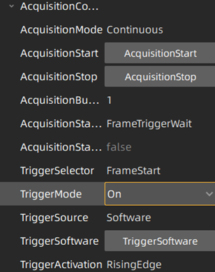
Verwenden Sie die Galaxy SDK Software, um eine Verbindung zur Kamera herzustellen und Folgendes einzustellen:
TriggerMode = On
Schritt 2: Wählen Sie die Triggerquelle aus
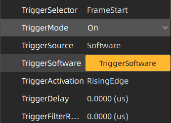
Software-Trigger → Auslösung durch Drücken der TriggerSoftware-Taste.
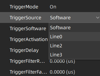
Hardware-Trigger → Wählen Sie die Eingangsleitung aus, an der der Trigger empfangen wird, z. B. line0.
Schritt 3: Trigger-Einstellungen optimieren
Verbessern Sie die Trigger-Reaktion durch Anpassung von Parametern wie:
- Steigende Flanke / Fallende Flanke – Definiert die Methode zur Trigger-Aktivierung.
- Trigger-Verzögerung – Passt das Timing zwischen Signal und Aufnahme an.
- Trigger-Filter – Reduziert unerwünschte Störgeräusche.
3. Anschluss eines Trigger-Sensors an eine Machine Vision Kamera
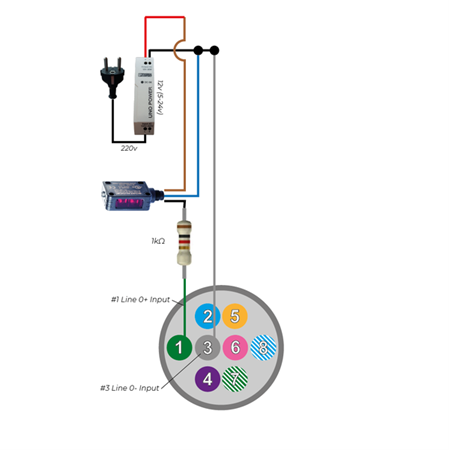
Beispiel: Verwendung eines retroreflektierenden Sensors
In dieser Konfiguration erkennt ein retroreflektierender Fotosensor (S100-PR-5-C10-PK) Objekte und sendet ein Triggersignal an die Kamera. Wenn ein Objekt den reflektierten Lichtstrahl des Sensors unterbricht, erhält der Eingangspin der Kamera Strom, wodurch die Bildaufnahme ausgelöst wird.
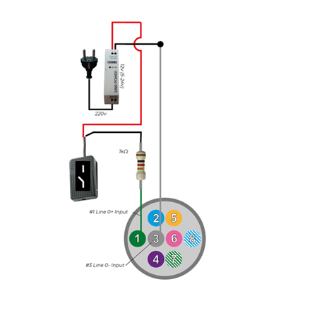
Beispiel: Verwendung eines Fußpedalschalter
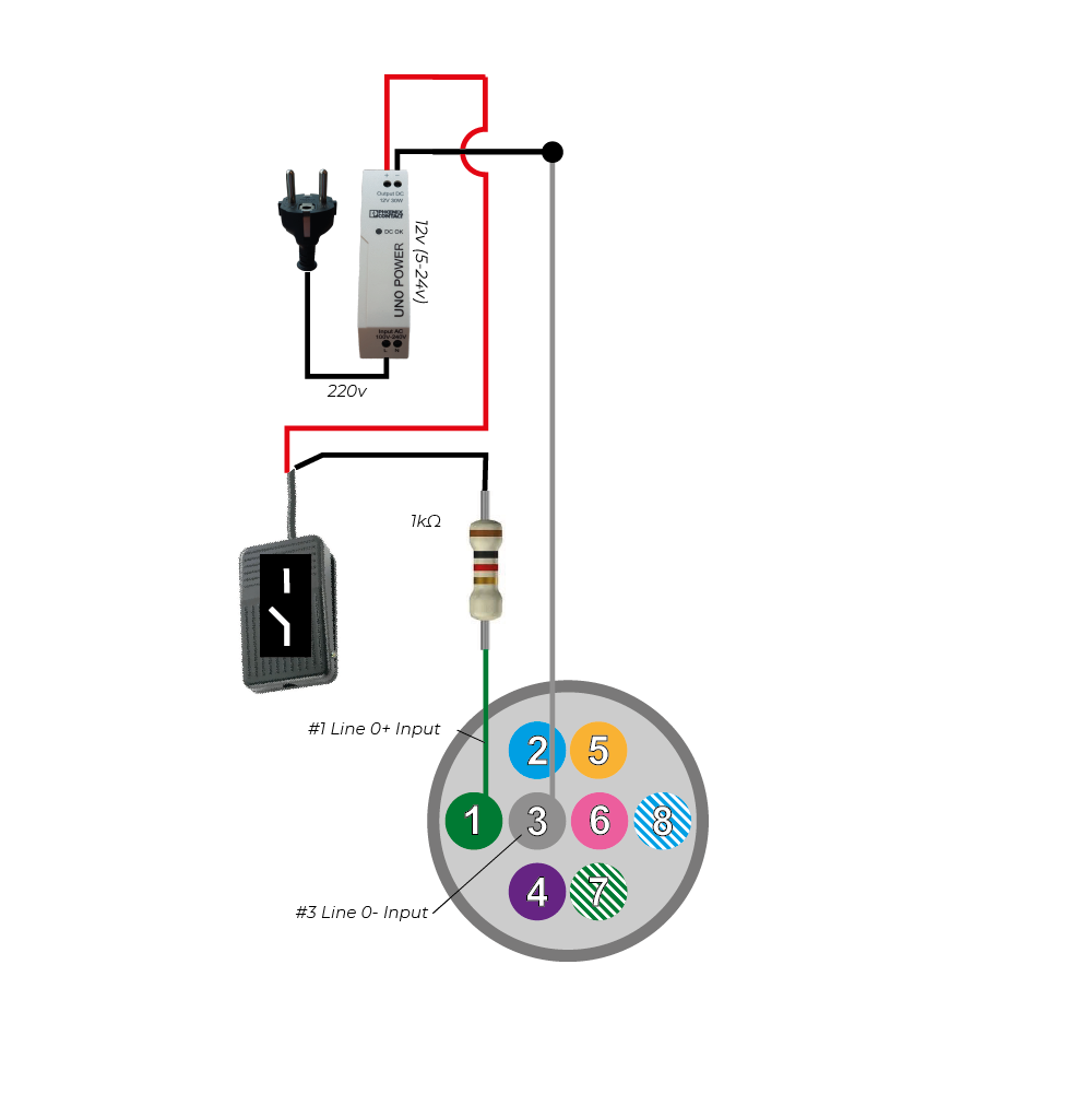
Ein Fußschalter (FS-01) oder jeder analoge Kippschalter (Stromkreis öffnen/schließen) kann ebenfalls als Auslöser verwendet werden. Das Betätigen des Pedals schließt den Stromkreis und sendet ein Signal an die Kamera.
4. Verwendung einer Machine Vision Kamera zur Auslösung eines Stroboskoplichts
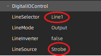
Um eine Lichtquelle auszulösen, ordnen Sie die Strobe-Funktion der Kamera einer ihrer Ausgangsleitungen zu:
Definieren Sie Line1 als Ausgang
Setzen Sie LineSource = Strobe
Wenn die Kamera bereit ist, Licht zu erfassen, sendet der Strobe-Ausgang ein Hochspannungssignal. Das Signal bleibt niedrig, wenn keine oder nur ein Teil der Pixel bereit sind, Licht zu erfassen.
Hinweise zu Global vs. Rolling Shutter Kameras
Global Shutter: Alle Pixel erfassen das Licht gleichzeitig.
Rolling Shutter: Pixel erfassen nacheinander; das Strobe-Signal wird nach 1/framerate aktiviert (z. B. 50 FPS → 20 ms Verzögerung).
Für rolling shutter Kameras funktioniert das Strobe-Signal nur, wenn die Belichtungszeit größer als 1/framerate ist. Weitere Informationen finden Sie unter QuickStart: 5 Schritte zum Auslösen einer LED von einer Vision Kamera mit Strobe-Controller.
5. Synchronisierung mehrerer Kameras (Master/Slave-Konfiguration)
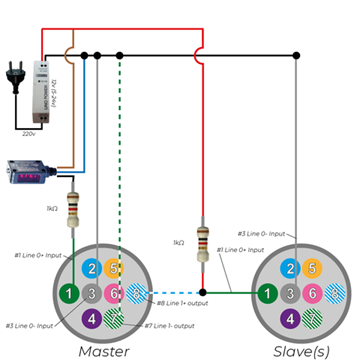
Beispiel für das Auslösen von Master-Slave-Kameras
Nachfolgend ist ein Beispiel dargestellt, bei dem eine Master-Kamera durch einen Lichtschranken-Sensor ausgelöst wird und eine Slave-Kamera mit der Master-Kamera synchronisiert ist.
Wenn der Triggersensor aktiviert wird, gibt er ein Hochspannungssignal aus, wodurch auch Pin 1 der Master-Kamera auf High geht.
Sobald eine steigende Flanke an Pin 1 der Master-Kamera erkannt wird, öffnet die Kamera die Verbindung zwischen Pin 7 und Pin 8, sobald alle Pixel bereit sind, Licht zu erfassen. Standardmäßig sind die Pins 7 und 8 normalerweise geschlossen (NC).
Elektrisches Verhalten:
Wenn die Pins 7 und 8 geschlossen sind:
Die Spannung an beiden Pins ist niedrig und daher bleibt auch Pin 1 der Slave-Kamera niedrig.
Dann fließt der Strom von der 24V-Stromversorgung über einen 1K-Widerstand (zur Strombegrenzung), dann durch Pin 8 und Pin 7 der Master-Kamera und zurück zur Masse der Stromversorgung.
Wenn die Pins 7 und 8 offen sind:
Die Spannung an Pin 7 bleibt niedrig, während Pin 8 der Master-Kamera auf High geht. Folglich geht auch Pin 1 der Slave-Kamera auf High.
Der Strom fließt nun von der 24V-Stromversorgung über den 1K-Widerstand durch Pin 1 der Slave-Kamera und schließlich über Pin 3 der Slave-Kamera zurück zur Masse der Stromversorgung.
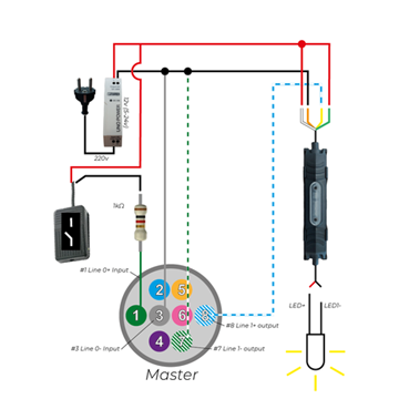
6. Auslösen eines Strobe-Controllers mit einer Machine Vision Kamera
Eine Machine - vision Kamera kann auch verwendet werden, um über einen Strobe-Controller eine externe Lichtquelle auszulösen. Weitere Informationen finden Sie hier.
In dieser Konfiguration:
· Die Kamera erzeugt ein Triggersignal beim Aufnehmen eines Bildes. Dieses Signal wird an den Strobe-Controller gesendet.
· Nach Empfang des Triggers versorgt der Strobe-Controller das LED-Licht mit Strom. Der Strobe-Ausgang liefert ein Hochspannungssignal, wenn alle Pixel der Kameras bereit sind, Licht zu erfassen. (Bei einer global Shutter Kamera sind alle Pixel gleichzeitig bereit. Bei Rolling Shutter Kameras gibt es eine Verzögerung von etwa 1/Bildrate, bevor alle Pixel bereit sind.)
· Das LED-Licht ist mit dem Ausgang des Strobe-Controllers verbunden.
· Ein analoger Fußschalter ist ebenfalls mit dem Eingang der Kamera verbunden. Dies ermöglicht das manuelle Auslösen der Kamera, wodurch wiederum die Lichtquelle ausgelöst wird.
7. I/O-Port-Konfigurationen & Spannungsüberlegungen
Bei der Integration einer industriellen Machine Vision Kamera ist es wichtig, die Unterschiede zwischen den GigE- und USB3-Kamera-Pinbelegungen zu beachten:
- GigE Kameras: Bieten die Möglichkeit, über den I/O-Anschluss mit Strom versorgt zu werden
- USB3 Kameras: Sind immer auf die USB-Busspannung zur Stromversorgung angewiesen und können nicht über den I/O-Anschluss mit Strom versorgt werden.
Dieser Unterschied wirkt sich nicht auf die Schaltpläne zur Auslösung der Kamera aus, ist jedoch bei der Planung der Stromversorgung Ihres Systems entscheidend.
Triggerkabel-Anschluss
Um ein Triggerkabel an Ihre Kamera anzuschließen, beachten Sie bitte die Handbücher MER2 GigE Kamera I/O und MER2 USB3 Kamera I/O. Sie können diese auf unserer Download-Seite herunterladen.
8. Erweiterte Triggerfunktionen
Wir empfehlen, Leitung 0 als Kamera-Eingang und Leitung 1 als Kamera-Ausgang zu verwenden. Diese Leitungen sind optisch isoliert und gewährleisten eine erhöhte Zuverlässigkeit sowie Störsicherheit.
Spannungsspezifikationen: Für Leitung 0 & Leitung 1 (optisch isoliert)
- Logik 0 (Keine Aktion): 0 V – +2,5 V
- Logik 1 (Aktion ausgelöst): +5 V – +24 V
Strombereich: 7 mA – 25 mA | Für Spannungen über 9 V wird ein strombegrenzender Widerstand empfohlen.
Spannungsspezifikationen: Für Leitung 2 & Leitung 3
Für erweiterte Funktionalität (bei Bedarf an mehreren I/Os) können Leitung 2 und Leitung 3 entweder als Eingänge oder Ausgänge konfiguriert werden.
- Logik 0 (Keine Aktion): 0 V – +0,6 V
- Logik 1 (Aktion ausgelöst): +1,9 V – +24 V
Hinweis: Wenn Sie Leitung 2/3 als Eingänge konfigurieren, vermeiden Sie Pull-Down-Widerstände über 1 kΩ, da diese dazu führen können, dass die Eingangsspannung 0,6 V überschreitet und somit die korrekte Erkennung von Logik 0 verhindert wird. Um Schäden an den GPIO-Pins zu vermeiden, schließen Sie immer zuerst den GND-Pin an, bevor Sie Spannung an Leitung 2/3 anlegen.
9. Zusätzliche Triggerfunktionen
Die Hardware-Auslösung bietet verschiedene Funktionen und Optionen, um die Zuverlässigkeit und Genauigkeit Ihres Kamera-Systems zu verbessern:
- Rising/Falling Edge Delay: Definiert die Zeit, die die Kamera benötigt, um zu bestätigen, dass ein gültiges Triggersignal eingegangen ist.
- Frame Trigger Wait: Stellt sicher, dass der Kamera-Ausgang so lange auf High bleibt, bis die Kamera bereit ist, den nächsten Hardware-Trigger zu empfangen. Diese Einstellung ermöglicht die höchstmögliche Trigger-Rate.
- Input Debouncer: Filtert Kurzzeitimpulse heraus, indem eine minimale gültige Signaldauer für sowohl steigende als auch fallende Flanken festgelegt wird. Dies hilft, Fehltriggerungen durch Störungen zu vermeiden.
- Trigger Delay: Führt eine definierte Verzögerung zwischen dem Moment der Trigger-Bestätigung und der Ausführung der Trigger-Aktion durch die Kamera ein.
- Input Inverter: Ermöglicht es dem Benutzer, die Logik des Eingangssignals durch Konfiguration der Einstellung „LineInverter“ umzukehren.
10. Maßgeschneiderte I/O-Funktionen & RS232 Support
Wenn Ihre industrielle Kamera-Applikation maßgeschneiderte I/O-Funktionen erfordert, wie zum Beispiel die Nutzung von GPIO für RS232
Kommunikation, bieten wir maßgeschneiderte Firmware-Lösungen an.
Benötigen Sie eine maßgeschneiderte I/O-Konfiguration?
Kontaktieren Sie uns noch heute für maßgeschneiderte Lösungen, die auf Ihre spezifischen Anforderungen zugeschnitten sind.


